By Simon Jones
Burgoynes has investigated numerous water escapes in multi-storey buildings that incorporate boosted (pumped) water supplies. In many instances the cause of the leak has been traced to improperly installed plumbing fittings. However, boosted water supplies can create transient pressure shocks that can briefly exceed, by far, the normal system operating pressure and the maximum pump output pressure. Our involvement has led to the realisation that the causes of these pressure spikes are commonly misunderstood. Moreover, there is a scarcity of guidance concerning the appropriate design and use of such systems. This article attempts to provide an overview of - and dispel some of the more common myths surrounding - boosted water supplies.
Boosted water supplies usually comprise a mains fed cold water storage tank that is located on the lowest level of the building. The tank supplies a set of electrically driven pumps, arranged in parallel, that are controlled electronically. The outlet from the pump set is then connected to a large riser pipe that passes up through the building. Smaller pipes branch from the riser to supply the various floor levels. A non-return valve at the pump set prevents water that has been pumped up the riser from draining back into the tank when the pumps are switched off. An accumulator tank is also fitted at the outlet of the pump set.
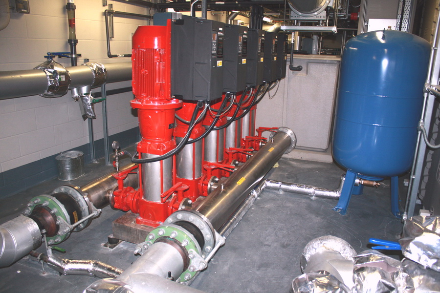
Accumulators allow the pressurised (pumped) water supply to partly fill a tank that is initially charged with pressurised air. The water and the air are separated by a rubber membrane, which allows pumping energy to be stored and released by the compression and expansion of the air. Thus, accumulators permit all the pumps to be switched off for short periods with no loss of water supply. To an extent, accumulators also damp out fluctuations in the supply pressure. An accumulator will only work if it is initially charged with air to a pressure that is less than the boosted water supply pressure (e.g. around 0.75 times the pump pressure set point).
The principle cause of large pressure surges in boosted water supplies is the high-speed filling of the riser pipework. This is because the kinetic energy of the fast moving water is converted to pressure energy when the water is stopped suddenly. This typically occurs when fast moving water reaches the top of the riser or the end of the distribution pipework. The phenomenon is sometimes called ‘water hammer’ and it tends to be worse when a vacuum has previously formed at the top of the riser, i.e. because water has been drawn out at a lower level when the pump set was not running. This means that one or more of the following events, all of which provide an opportunity for water to be drawn from the riser and the riser to then be refilled, usually initiate water hammer:
- Temporary power cuts;
- The pumps being switched off for maintenance and then switched back on;
- The water storage tank being too small or the mains supply to it being compromised;
- The booster pump set being incapable of filling the riser completely at times of high demand; or
- The accumulator failing and allowing brief breaks in the supply pressure when the control system switches between pumps (albeit to a lesser extent because of the more limited opportunity for water to be drawn from the riser).
Ultimately, the peak pressure that can be created is not limited by the maximum pressure output of the pumps, but by the maximum flow rate that the pumps can provide and the manner in which the water is arrested. An analogy to this would be the pushing of a car by a lone person that applies a relatively low force. If that car is pushed for a period of time it will build up speed (kinetic energy) which, if the car is stopped suddenly by an impact, will result a brief high force.
Considering the above, the most obvious way to prevent water hammer is to size the pump set so that it will readily cope with high demand1 and control the filling operation following shut-downs or low-pressure events. The latter can be achieved by setting the control system and the pumps to shut down and thereby force a manual reset following a power cut or after any period during which the output pressure is insufficient to reach the top of the building.
Some knowledge and skill is necessary when the pump set is manually restarted. In fact, a restart is liable to end in a ‘bang’ if someone simply switches the pump set back on. In general, a suitable procedure would involve an isolation valve near the bottom of the riser being closed manually, the pump set being switched on and limited to one pump if possible, and the isolation valve being opened partially so that it limits the fill rate of the riser. Only when the riser has filled and the supply pressure has stabilised to the normal level should the isolation valve be opened fully and the operation of the pump set be switched to automatic.
With the above in mind, modern control units tend to incorporate filling modes that operate automatically when the pressure is less than that which is required to fill the riser. A filling mode should limit the flow rate until the output pressure has risen to a level that is sufficient to show that the riser has filled, which can be achieved with a variable speed drive pump or a smaller, ‘jockey’ pump. Careful set-up is required to ensure that the filling mode is activated and operates as intended and that the pumps will not, for example, enter a full speed condition following a power cut before the control unit has initiated itself.
It appears that the failure to always implement a 100% effective system to prevent water hammer has led to the invention of various myths and devices, only some of which could theoretically work at all.
Firstly, it is sometimes believed that pressure surges can be prevented by fitting a pressure reducing valve (PRV) between the pump set and the riser. Since PRVs are intended to limit the supply pressure and not the flow rate, the inclusion of one is unlikely to offer any significant protection against water hammer.
Another misconception is that modern variable speed drive pump motors prevent pressure surges because the supply pressure is ramped up automatically. In practice, variable speed drive pumps tend to be brought up to full speed so quickly that the maximum flow rate will be reached well before the riser is filled after it has been allowed to drain down. To an extent, this is intertwined with another set-up problem: Pump systems should be set to switch on multiple pumps at times of high demand, when the normal supply pressure cannot be attained with one pump, otherwise, water hammer due to incomplete filling would be likely. However, extra pumps should only be switched on if there is already sufficient output pressure to reach the top of the building. In contrast, it seems that some pump sets are incorrectly programmed to switch on more than one pump during any low pressure situation (including filling), which could increase the flow rate and exacerbate a water hammer episode.
There are some valves on the market that are intended to limit the peak pressure that can occur, even if all the pumps are switched on after a shut-down. These are typically referred to as ‘anti-shock’ or 'anti-surge' valves and they are fitted to the tops of risers. The valves allow air to be drawn into the top of the riser if the water pressure at that point falls below atmospheric pressure (i.e. when a partial vacuum is present at the top of the riser). When the water supply pressure is restored the anti-shock valve should allow the air to escape slowly from the riser, limiting the refill rate and thereby limiting the potential for water hammer. From a theoretical point of view these ought to be relatively effective but, just in case, it might not be advisable to test one in situ. One word of caution is that anti-shock valves are almost invariably fitted beyond an isolation valve for maintenance purposes. The isolation valves are sometimes closed because of a misunderstanding or a minor leak from the anti-shock valve and the system will then continue to operate normally until the next water hammer event.
We have also seen small expansion vessels fitted to the tops of risers in an attempt to limit the peak pressure that can occur during a water hammer incident. In effect, the expansion vessels are intended to provide a cushion of air at the top of the riser. In practice, the expansion vessel would need to be large enough that it did not become almost completely filled with water during an impact for it to have a significant effect. The air charge would also need to be maintained periodically.
Finally, while our engineers routinely deliberate over the complex issues concerning boosted water supplies, the above article only broadly outlines the more common problems. Moreover, precise numbers are difficult to provide because system testing would be required and building owners have traditionally been reluctant to allow us to duplicate fault conditions and measure the peak pressure.
1. At times of low demand it is more energy efficient to use a small pump. Hence, several small pumps arranged in parallel should be more economical to run than a single large variable speed drive pump. Systems with multiple pumps also have built-in redundancy and more easily permit maintenance.
2. That is not to say that PRVs have no place in boosted systems. For example, PRVs can allow different height risers in the same building to be connected to the same pump set at different pressures, or provide a steady supply pressure from fixed drive speed pumps that operate between upper and lower pressure points.
For further details please contact
Simon Jones, London Office